Adc Averaging Results One Shot or Continuous
This driver configures and controls the SAR ADC subsystem block.
The functions and other declarations used in this driver are in cy_sar.h. You can include cy_pdl.h to get access to all functions and declarations in the PDL.
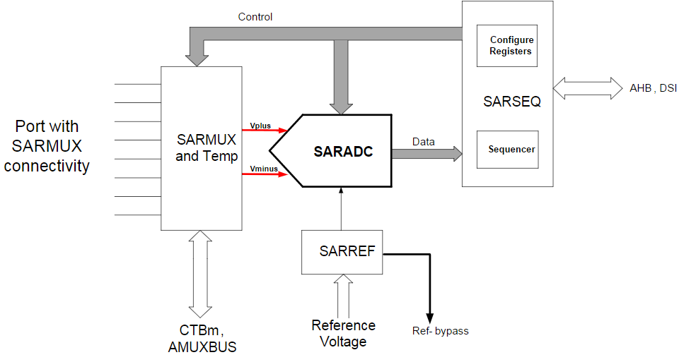
This SAR ADC subsystem is comprised of:
- a 12-bit SAR converter (SARADC)
- an embedded reference block (SARREF)
- a mux (SARMUX) at the inputs of the converter
- a sequence controller (SARSEQ) that enables multi-channel acquisition in a round robin fashion, without CPU intervention, to maximize scan rates.
The high level features of the subsystem are:
- maximum sample rate of 1 Msps
- sixteen individually configurable channels (depends on device routing capabilities)
- per channel selectable
- single-ended or differential input mode
- input from external pin (8 channels in single-ended mode or 4 channels in differential mode) or from internal signals (AMUXBUS, CTB)
- choose one of four programmable acquisition times
- averaging and accumulation
- scan can be triggered by firmware or hardware in single shot or continuous mode
- hardware averaging from 2 to 256 samples
- selectable voltage references
- internal VDDA and VDDA/2 references
- buffered 1.2 V bandgap reference
- external reference from dedicated pin
- interrupt generation
Configuration Considerations
As an example, following SAR configuration will be used:
- Three channels:
- Single-ended channel on Pin 0
- Single-ended channel on Pin 1
- Differential channel between Pin 0 (positive input) and Pin 1 (negative input)
- 12-bit resolution for all three channels
- No sample averaging for all three channels
- Trigger SAR from TCPWM-based timer.
The high level steps to use SAR driver are:
- Configuration structure
- Initialization and Enable
- SAR Clock Configuration
- Triggering Conversions
- Handling Interrupts
- Retrieve Channel Results
Configuration structure
To configure the SAR subsystem, call Cy_SAR_Init. This function requires two pointers: a pointer to the SAR_Type structure for the base hardware register address and pointer to the configuration structure cy_stc_sar_config_t.
Configuration structure cy_stc_sar_config_t includes two substructures: cy_stc_sar_config_t::channelConfig and cy_stc_sar_config_t::routingConfig.
cy_stc_sar_channel_config_t is used to configure individual channels. Here is an example of SAR channels configuration for our use case:
{
false,
false,
0UL,
false,
false
};
{
false,
false,
0UL,
false,
false
};
{
CY_SAR_ADDR_SARMUX_0,
true,
false,
0UL,
false,
false
};
cy_stc_sar_routing_config_t is used to define SARMUX configuration. Use one or more values from the SARMUX Switch Control Register Masks and "OR" them together. Firmware control can be changed at run-time by calling Cy_SAR_SetAnalogSwitch the desired switch states SARSEQ control can be changed at run-time by calling Cy_SAR_SetSwitchSarSeqCtrl.
In order to complete SAR configuration structure, all remaining fields of cy_stc_sar_config_t should be filled:
{
false,
CY_SAR_NEG_SEL_VSSA_KELVIN,
CY_SAR_NEGVREF_HW,
true,
false,
false,
CY_SAR_SUB_RESOLUTION_8B,
false,
true,
true,
CY_SAR_AVG_CNT_2,
true,
false,
4UL,
4UL,
4UL,
4UL,
0x300UL,
0xC00UL,
CY_SAR_RANGE_COND_OUTSIDE,
0x07UL,
{&channelSe0Cfg, &channelSe1Cfg, &channelDiffCfg, NULL, NULL, NULL, NULL, NULL, NULL, NULL, NULL, NULL, NULL, NULL, NULL, NULL, NULL},
&routingConfig,
3300UL
};
Initialization and Enable
As mentioned in a previous step, to configure the SAR subsystem, call Cy_SAR_Init function with pointers to SAR_Type and cy_stc_sar_config_t structures. After initialization, call Cy_SAR_Enable to enable the hardware.
SAR Clock Configuration
The SAR requires a clock. Assign a clock to the SAR using the pre-defined enum, PCLK_PASS_CLOCK_SAR, to identify the SAR subsystem. Set the clock divider value to achieve the desired clock rate. The SAR can support a maximum frequency of 18 MHz.
Triggering Conversions
The SAR subsystem has the following modes for triggering a conversion:
| Mode | Description | Usage |
|---|---|---|
| Continuous | After completing a scan, the SARSEQ will immediately start the next scan. That is, the SARSEQ will always be BUSY. As a result all other triggers, firmware or hardware, are essentially ignored. | To enter this mode, call Cy_SAR_StartConvert with CY_SAR_START_CONVERT_CONTINUOUS. To stop continuous conversions, call Cy_SAR_StopConvert. |
| Firmware single shot | A single conversion of all enabled channels is triggered with a function call to Cy_SAR_StartConvert with CY_SAR_START_CONVERT_SINGLE_SHOT. | Firmware triggering is always available by calling Cy_SAR_StartConvert with CY_SAR_START_CONVERT_SINGLE_SHOT. To allow only firmware triggering, or disable hardware triggering, set up the cy_stc_sar_config_t::trigMode field of config structure with CY_SAR_TRIGGER_MODE_FW_ONLY. |
| Hardware edge sensitive | A single conversion of all enabled channels is triggered on the rising edge of the hardware trigger signal. | To enable this mode, set up the cy_stc_sar_config_t::trigMode field of config structure with CY_SAR_TRIGGER_MODE_FW_AND_HWEDGE. |
| Hardware level sensitive | Conversions are triggered continuously when the hardware trigger signal is high. | To enable this mode, set up the cy_stc_sar_config_t::trigMode field of config structure with CY_SAR_TRIGGER_MODE_FW_AND_HWLEVEL. |
If the trigger occurs during a scan, a CY_SAR_INTR_FW_COLLISION interrupt occurs and the trigger is delayed until the end of the scan.
The trigger mode can be changed during run time with Cy_SAR_SetConvertMode.
For the hardware trigger modes, use the TrigMux (Trigger Multiplexer) driver to route an internal or external signal to the SAR trigger input. When making the required Cy_TrigMux_Connect calls, use the pre-defined enum, TRIG6_OUT_PASS_TR_SAR_IN, for the SAR trigger input.
#if (defined(CY_DEVICE_PSOC4AS3) || defined(CY_DEVICE_PSOC4AS4) || defined(CY_DEVICE_PSOC4AMC))
#else
0 Response to "Adc Averaging Results One Shot or Continuous"
Post a Comment